Point in Case
One Scan, 900 Files?!

Real-world support cases explained – one point cloud at a time.
In this series, we take a closer look at real questions and challenges that come up when working with point cloud data. Each post is based on an actual support case and breaks down what happened, why it happened, and how to solve it, step by step.
But we don’t stop at troubleshooting. Along the way, we explain the background behind the tools, terms, and technologies involved.
The Question That Sparked This Post

“I imported just one scan… why do I have over 900 files now?”
If that sounds familiar, you’re not alone, and no, PointCab isn’t secretly duplicating your data. This exact situation came up in a recent support case, and it gave us the perfect opportunity to explain what’s really going on behind the scenes.
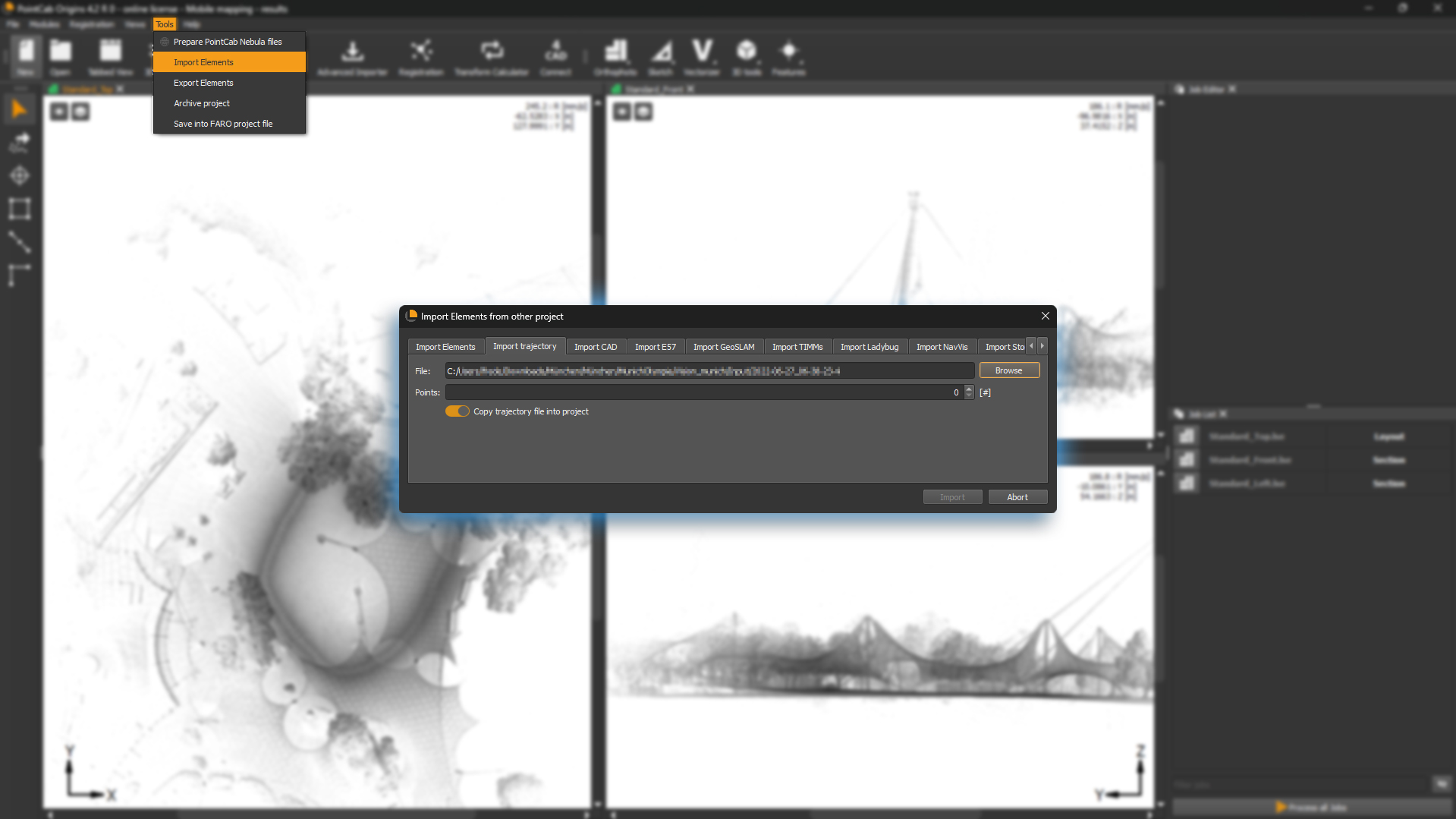
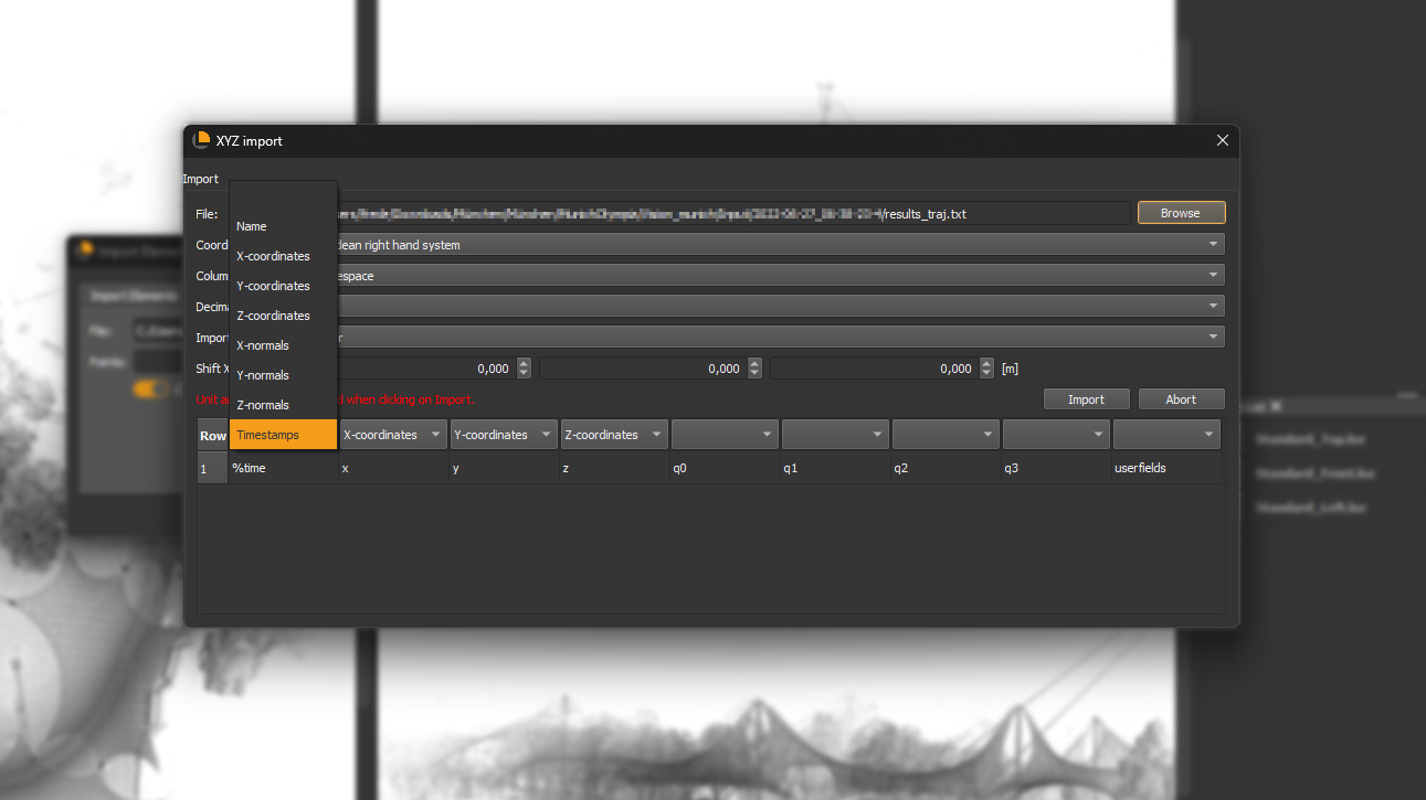
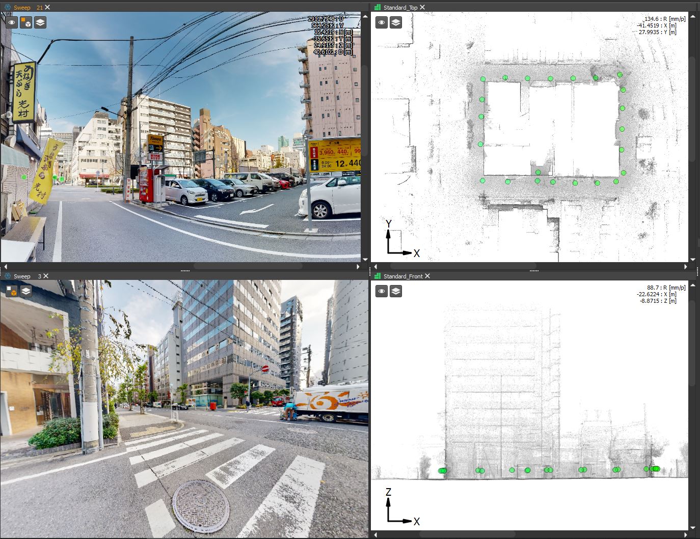
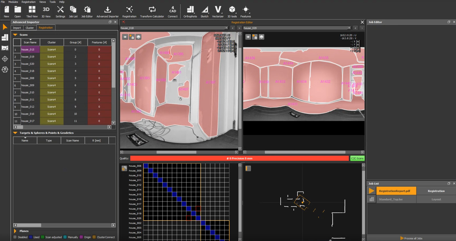
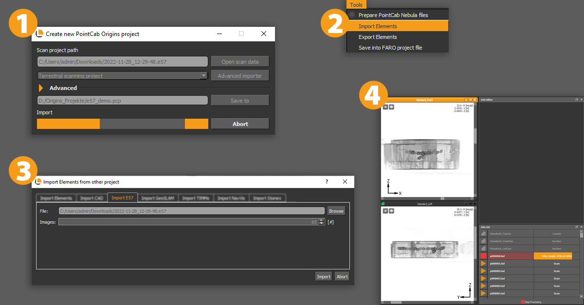
Our customer imported a single E57 scan exported from Riegl’s RiSCANpro into PointCab Origins. The result:
- Over 900 .lsd files created
- More than 700 tiles visible in the Top View
- And this was just one scan from a 30-scan project
The scan didn’t seem huge, so where did all those files come from? Let’s just say: it’s not a bug – it’s a feature. And a smart one at that.
The Key Context: Structured vs. Unstructured Point Clouds
Before diving into what happened, it helps to understand how point clouds are stored and why that matters when you import them into PointCab Origins.
Structured Point Clouds
- Come directly from scanners in their native formats
- Include metadata like scan positions and orientations
- Organized into scan stations or lines, each with a defined perspective
- Ideal for clean segmentation and accurate scan-to-scan alignment
Structured Point Clouds
- Formats like E57, LAS, or LAZ (especially when exported generically)
- Contain just the point data – no scan position, no segmentation
- All points are merged into a single cloud, with no “origin story”
- Often include stray points far outside the area of interest
Unstructured formats are great for software compatibility and flexibility, but they don’t tell the full story. That means software like Origins needs to rebuild structure to make the data usable. We explain this in more detail in our webinar on Structured vs. Unstructured Point Clouds, including why this difference affects file handling and performance.
What Origins Is Actually Doing
Now with this info in mind, let’s get back to the case at hand.
Origins doesn’t just render point clouds – it structures them so you can work with them efficiently.
Here’s what happens during import:
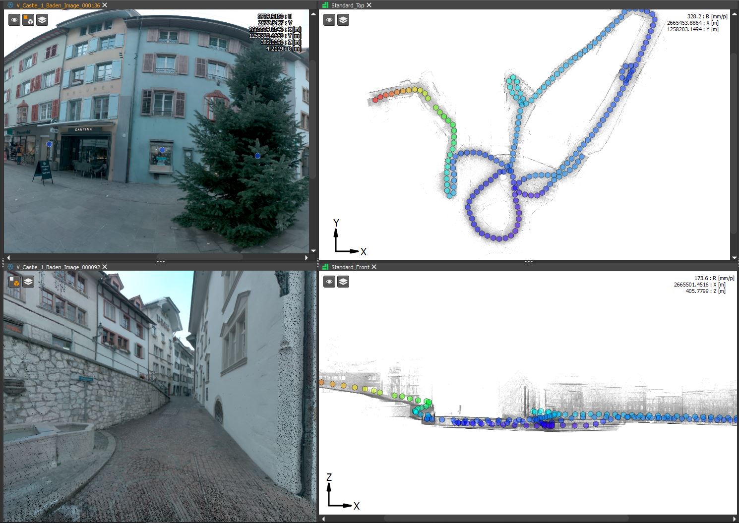
- Origins breaks the entire point cloud into a 3D grid of cubes, known as an octree.
- Each cube becomes a separate .lsd file, whether it contains thousands of points or just one.
- These cubes are the foundation for views like the Top View, Section Views, and more.
- If even one point lies far away from the main area, Origins generates all the intermediate cubes between that point and the rest of the data.
It’s kind of like paving a road to a remote cabin. You can’t just teleport there. Every step along the way needs to exist so the full path is usable.
What the User Saw
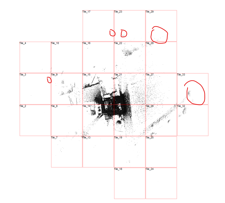
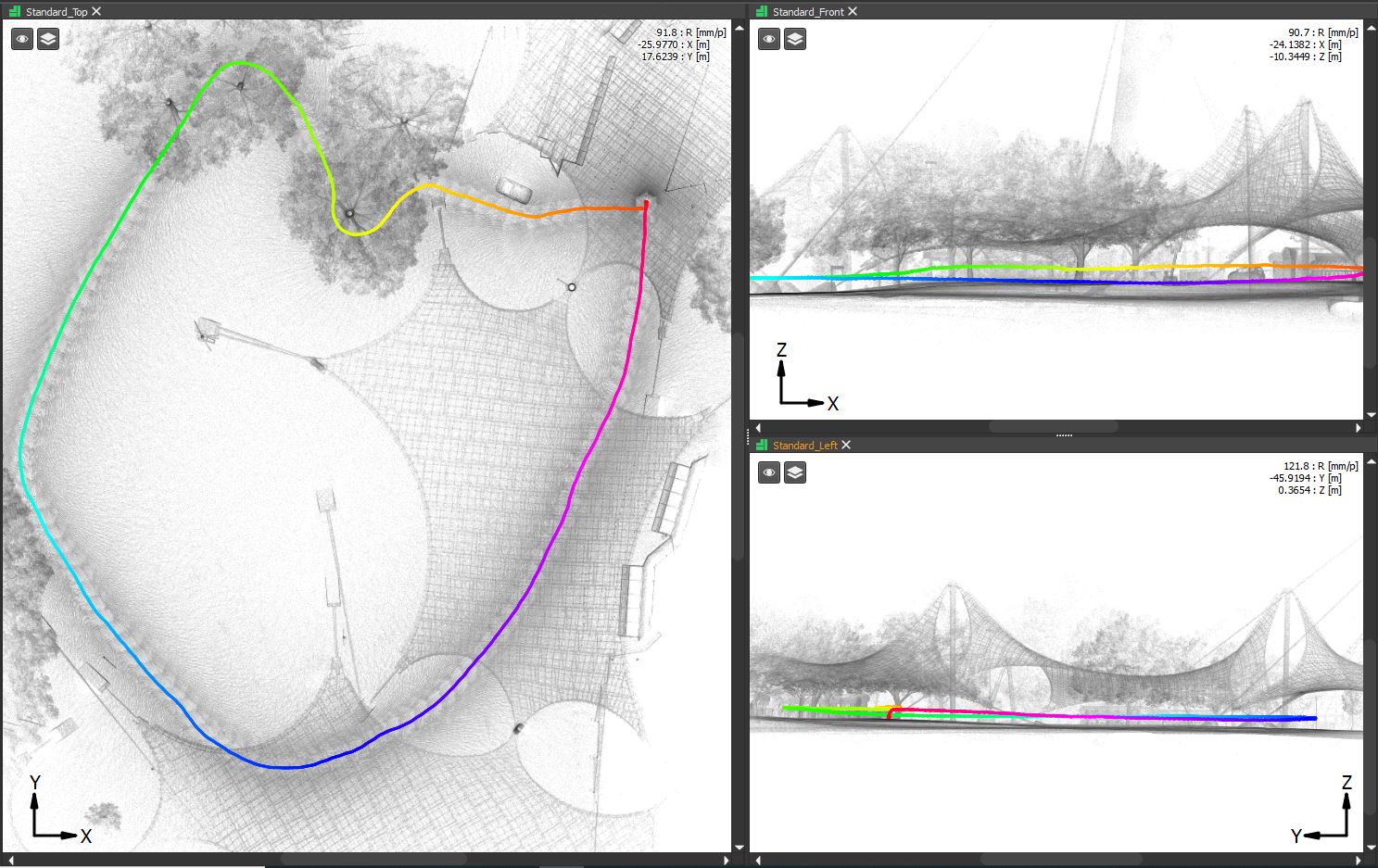
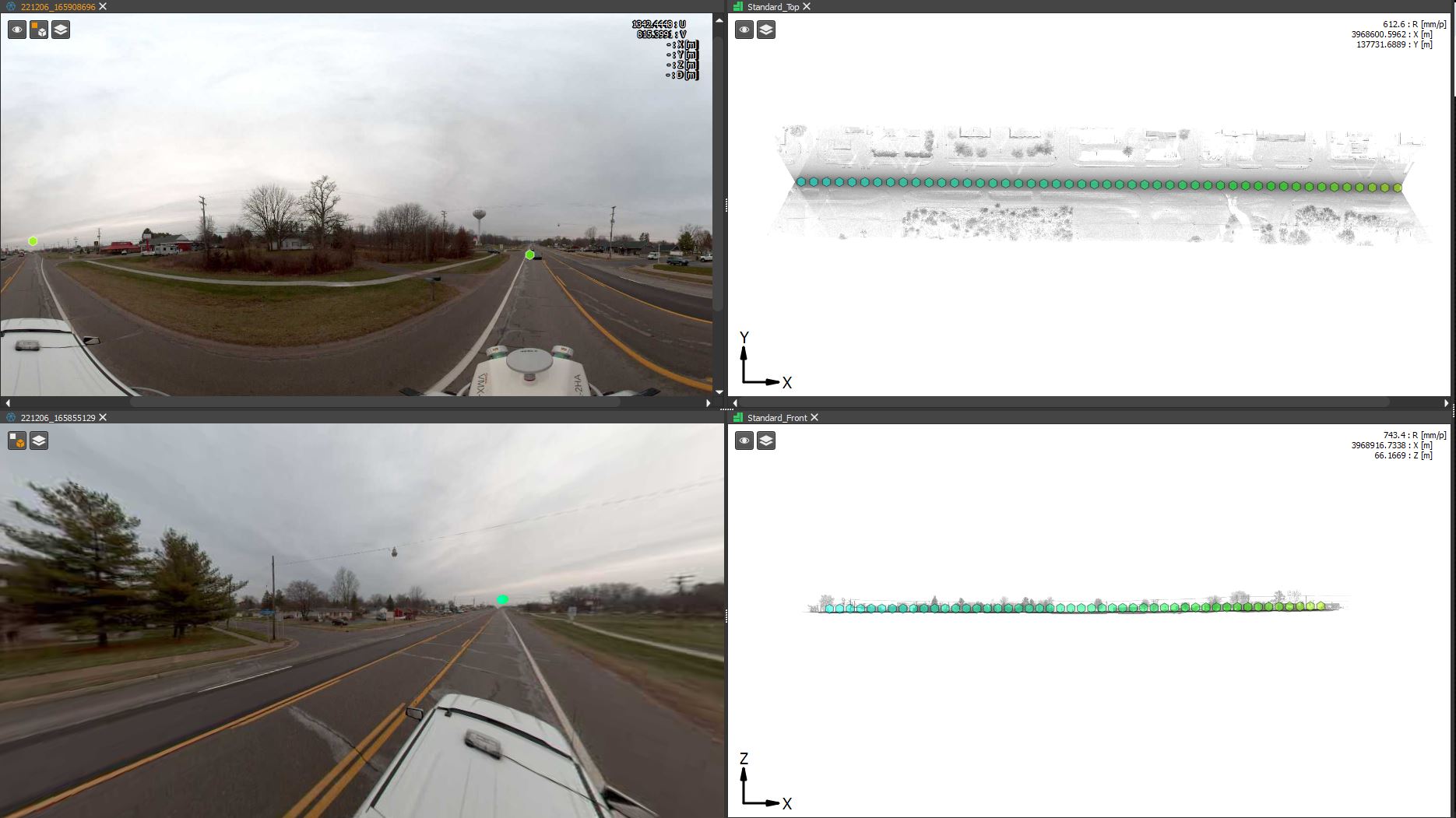
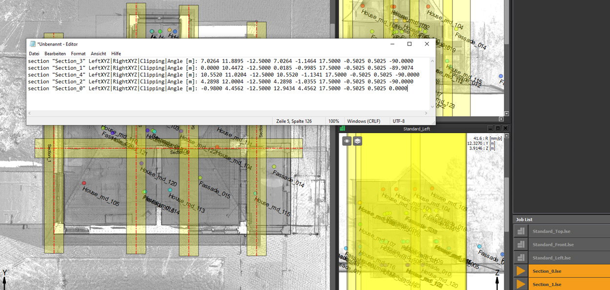
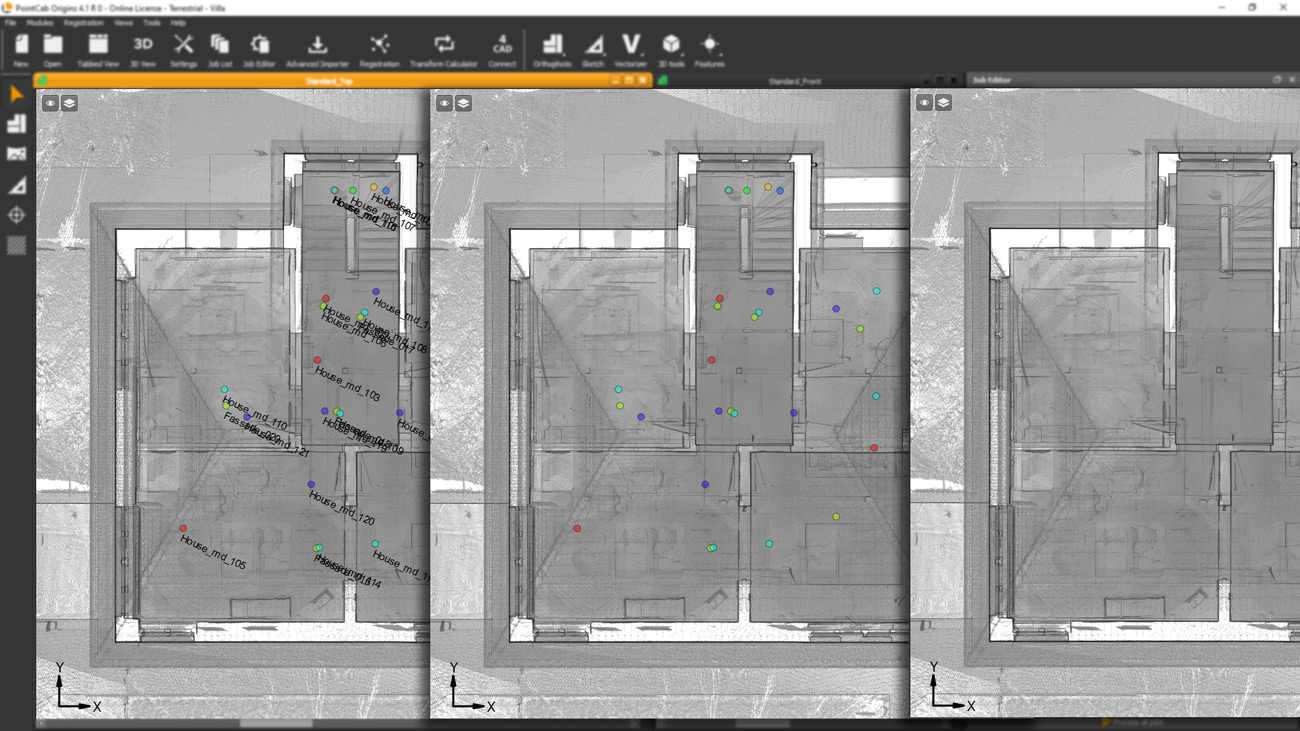
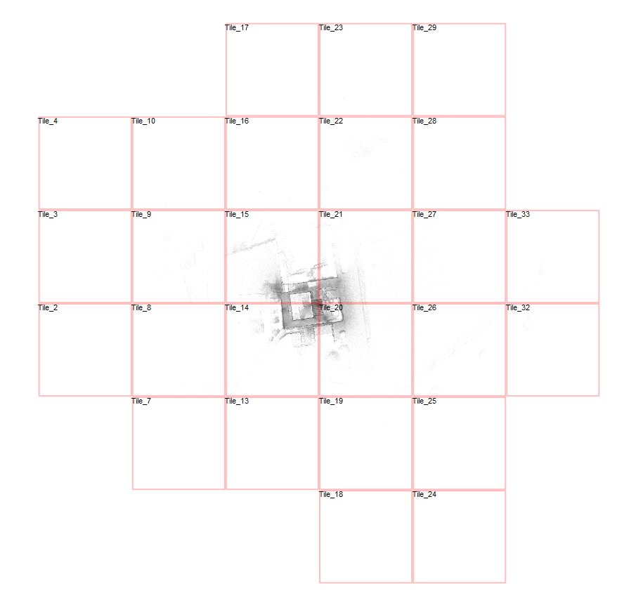
To understand the issue, we loaded the scan and pressed “B” in the Top View to toggle tile boundaries. The view showed:
- A scan area stretching around 500 meters wide
- And approximately 350 meters tall
So while the actual structure being scanned may have been compact, stray points – likely captured by the long-range scanner – extended the dataset much farther. And every bit of that range had to be included in the cube structure.
Is this a Problem and if so, how do I handle this?
Is this a problem? Not really.
Origins handles large numbers of .lsd files efficiently. Most of them are very small in size, and they don’t slow down performance unless the scan range is extremely large or your hardware is struggling.
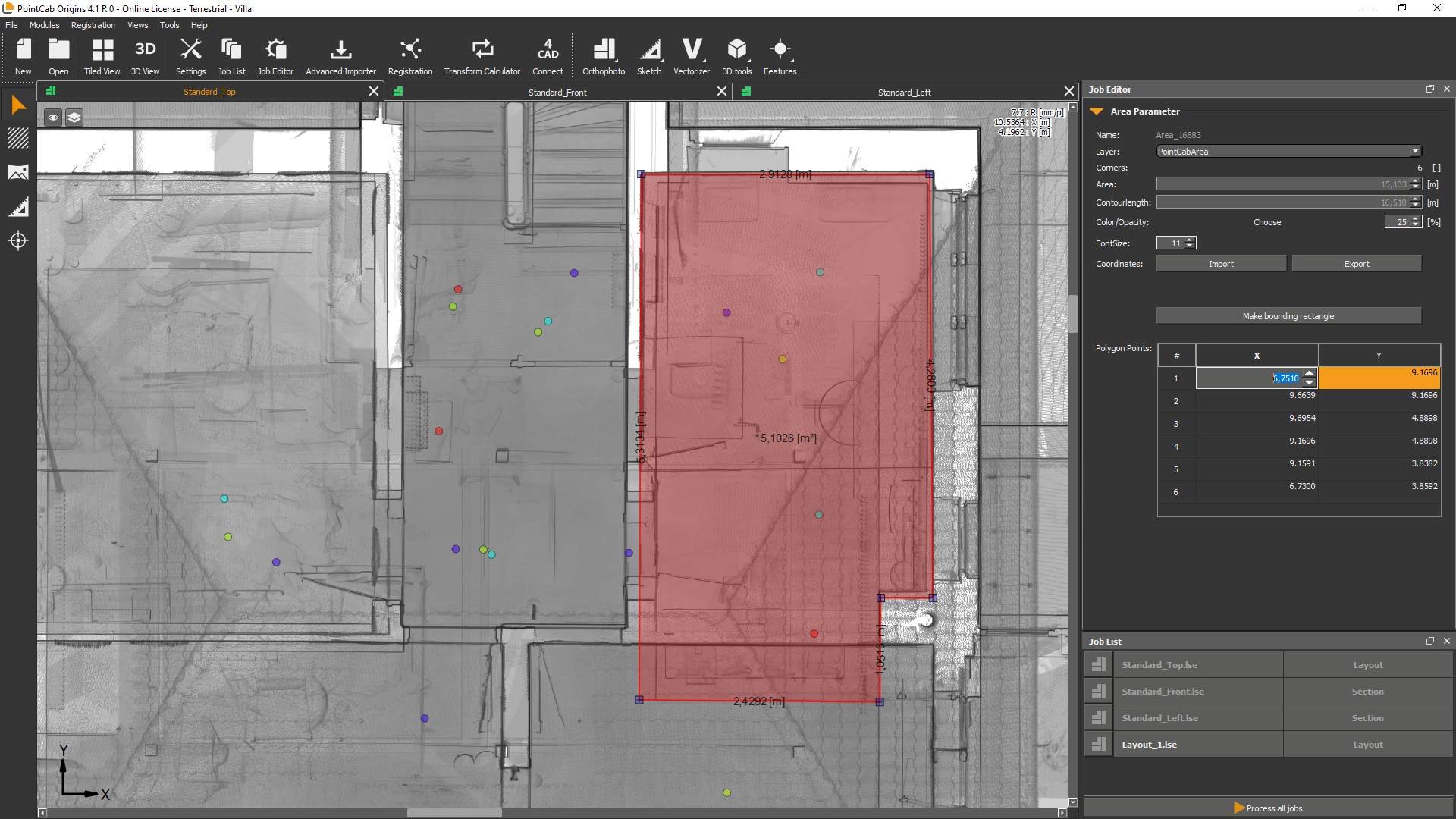
That said, a tighter Region of Interest can improve load times and keep your project folder cleaner, especially if you’re working with multiple scan areas or collaborating with others.
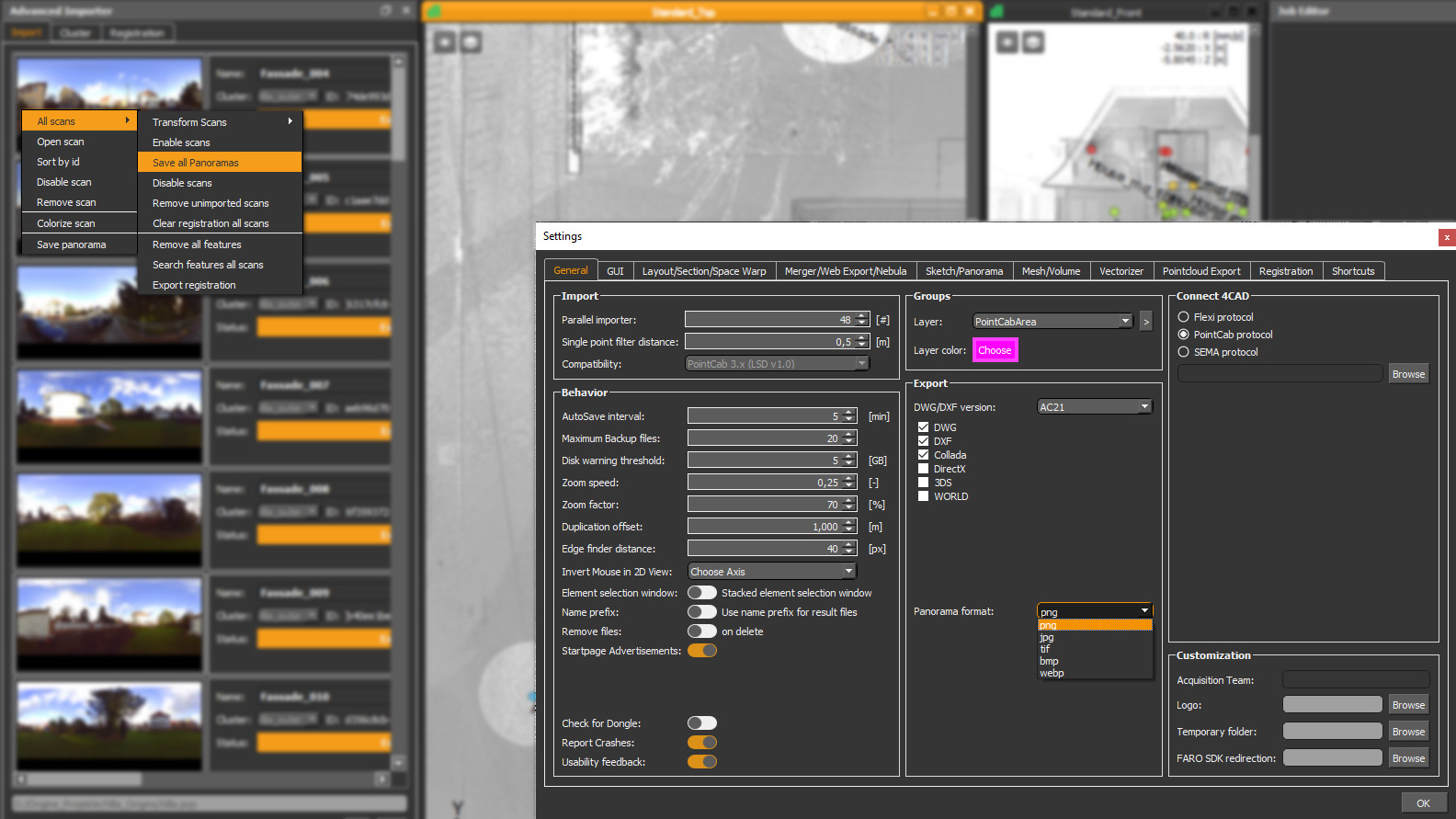
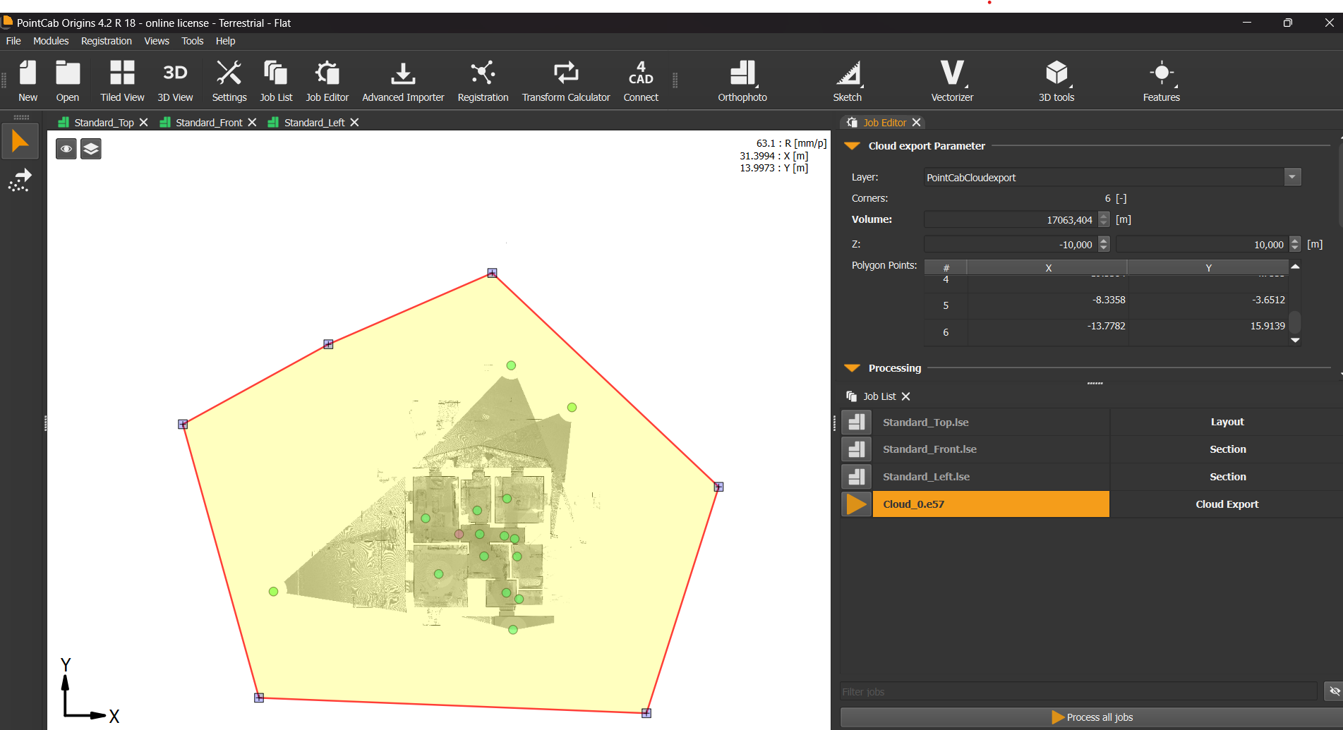
If you prefer a leaner project folder or faster loading times, you can reduce the number of files by tightening your import area:
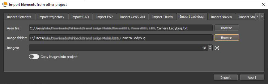
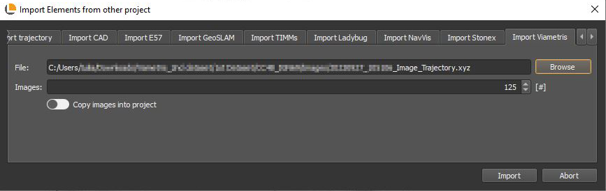
Import your scans into Origins as usual.
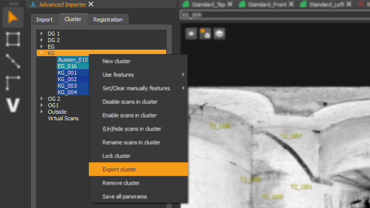
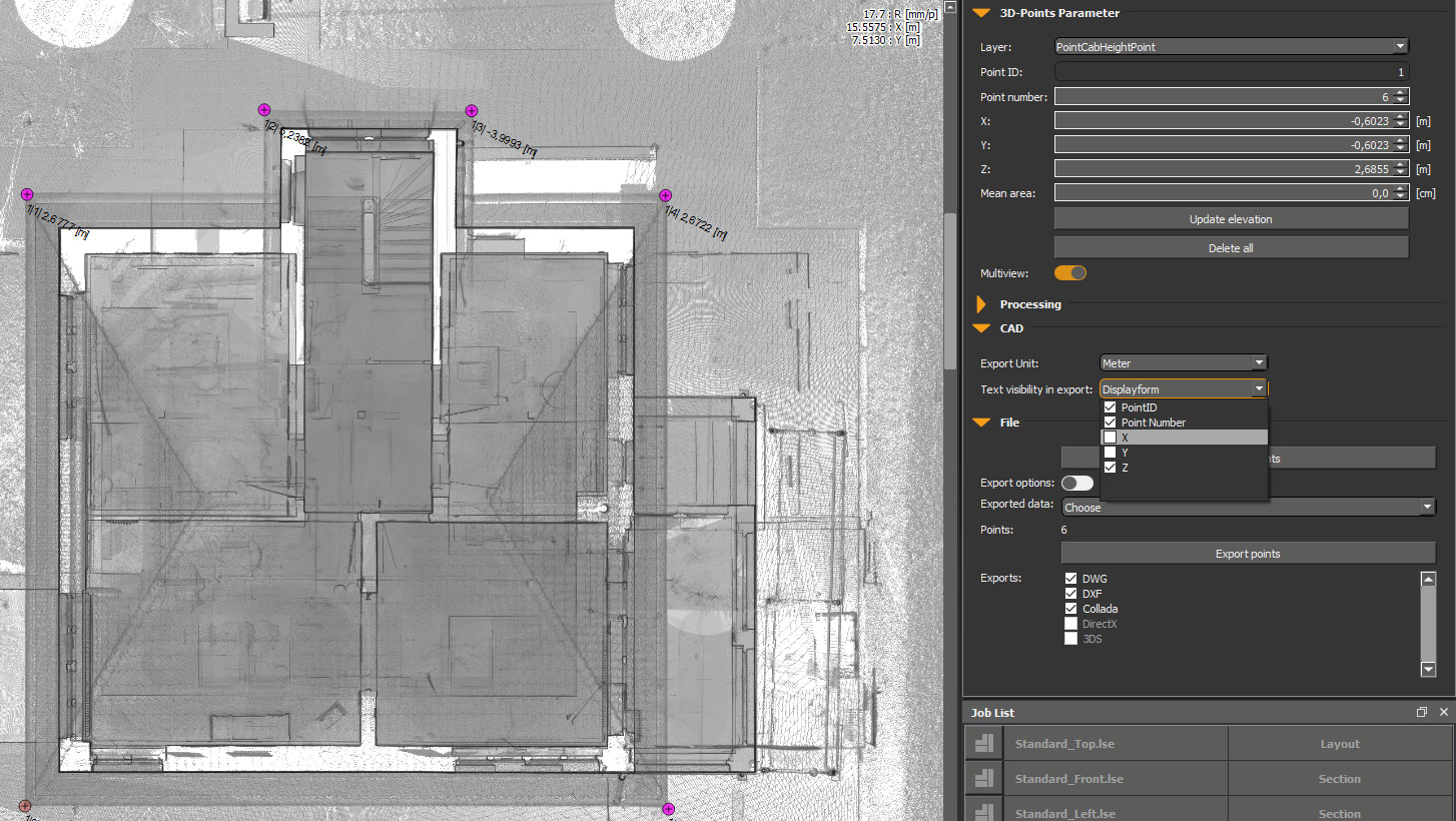
- Use the point cloud export tool to select a focused Region of Interest.
- Export just that area as a new point cloud.
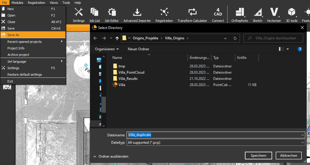
- Re-import the reduced file into a new PointCab project.
This keeps your file count – and disk space – under control while preserving all the data you actually need.
Final Thoughts
When a single scan suddenly turns into hundreds of files, it’s not Origins misbehaving – it’s Origins doing the hard work of organizing your data so you can actually use it.
If you’re ever unsure what’s going on behind the scenes, or want help optimizing your workflow, our support team is always happy to help. And if you want to better understand structured vs. unstructured data, check out our webinar on the topic.
Want to keep up with the latest pointCab news?
Then follow us on Social Media or subcribe to our newsletter!