Laser scanning technology helps preserve and repurpose a historic masonry building in Crete

blank

Laser scanning technology helps preserve and repurpose a historic masonry building in Crete

blank

Postgraduate students at the Technical University of Crete used a combination of a Trimble Laser Scanner, PointCab Origins Pro, and Autocad to obtain and document the exact geometry of a historic masonry structure with the purpose of its structural rehabilitation.

The island of Crete, Greece is known for its beautiful landscape and rich history. It’s the birthplace of the first European advanced civilization, the Minoans, and was shaped by the Mycenaeans, Romans, Osmans, and many more. The traces of these cultures can still be found all across the island in different archeological remains.

blank

One of them is a two-century-old residential masonry, built during the Osman rule. It has been abandoned for the last 70 years and is the former residence of the wealthy Seimeni family. As one of the few remaining buildings of that type of local architecture in the region, it bears great historic value. In order to preserve and repurpose the building, exact documentation of its geometry was required, among other factors, in order to assess its structural integrity and the degree of necessary strengthening interventions. The building is planned to be restored in the next years and to be used as a local folk art museum.

blank
blank

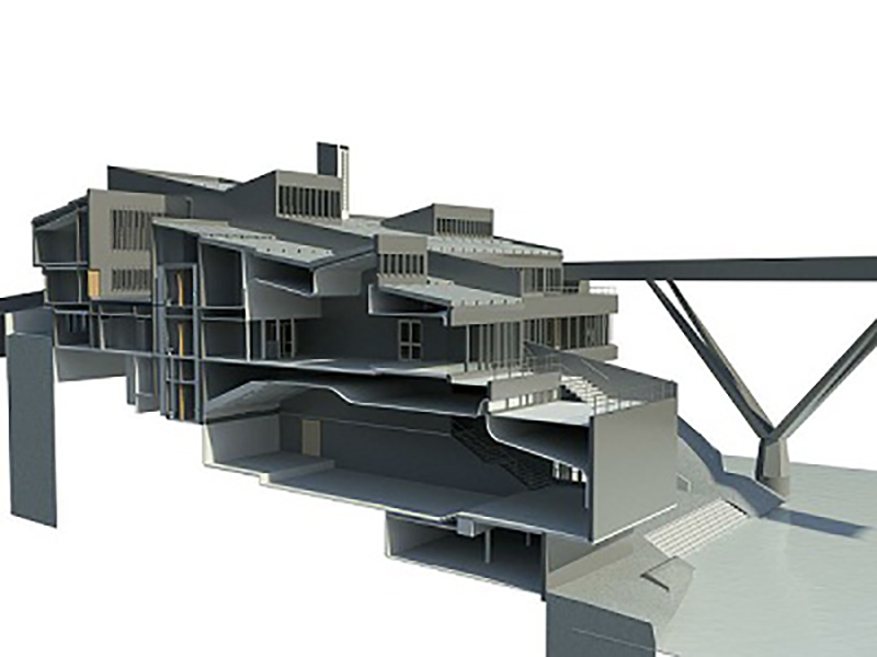
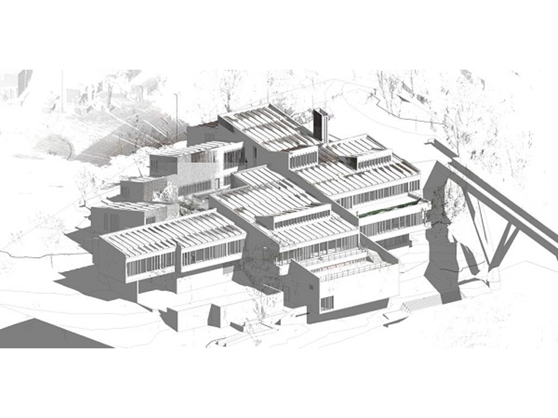
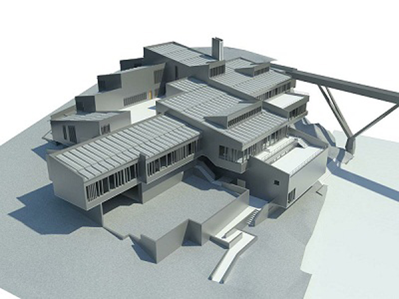
Postgraduate student Eirini Chorianopoulou, supervised by Professors Maria Stavroulaki and Nikos Skoutelis decided to exploit the benefits of the latest laser scanning technology available. Since there were parts of the building that could not be approached and a distant measurement technique was needed, using simpler tools and techniques would not suffice. Therefore, an accurate digital representation of the building in its condition before the restoration could be captured. 

This will give future visitors the chance to understand and compare the prior and current state and appreciate the work that will be done in order to preserve the authenticity of the structure after its restoration. With the purpose to obtain the geometric properties of the structure, the Trimble X7 3D laser scanner was employed. A number of 25 scans were used to generate the point cloud. All the data was imported as e57 format files and edited in PointCab Origins Pro. Accurate plans, sections, and elevations of the structure were created at all necessary levels and were exported as .dwg files for further editing in Autocad. Postgraduate researcher Evangelos Nitadorakis, responsible for handling the point cloud evaluation, found himself satisfied with the results that the use of PointCab’s Origins software provided: 

blank

“The accuracy of the generated sections allowed the identification and quantification of pathology indicators such as wall inclinations not visible with the human eye and remote measurements in parts of the structure that are not easily accessible. In addition, the delta analysis tool helped to distinguish even the slightest deviations in vertical levels. Furthermore, with a proper combination of all the data from Origins, an exact 3D model of the structure was created in a FEM analysis software and structural and dynamic analysis were conducted in order to assess the fragility of the structure under various loading cases. Employing PointCab Origins, we appreciated the easy handling, the speed of data processing, and the quality of the outcomes.”

blank
blank

What are point clouds?

Punktwolke point-cloud

WHAT ARE POINT CLOUDS?

Here’s an easy-to-understand introduction to the topic of point clouds. We answer the following questions:

Basics: What is a point cloud and how is it created?
What are point clouds used for?
How to work with point clouds? 

Punktwolke point-cloud

Basics: What is a point cloud and how is it created?

A point cloud can best be explained with the help of a gadget that reached the peak of its popularity in the 00s and is now primarily used for presentations: the laser pointer. The laser pointer can be used to illuminate a precise point in a straight line. If you know exactly where the laser pointer is located in the room, you can also exactly locate the point that is being illuminated. After all, the laser beam is straight as a die and thus makes it possible to calculate the exact position of the point in space in relation to the origin (the laser pointer). Geodetic points in surveying are also measured according to this basic principle, only it’s a little more complex. Instead of a laser pointer, special tachymeters are used for this purpose. 

And what does this have to do with point clouds? Quite simple. In addition to total stations, laser scanners have been used more and more frequently for surveying in recent years. These also work in the same way as our laser pointer, except that they can measure thousands or even millions of points simultaneously. Taken together, all the measured points constitue the point cloud. 

blank

What are point clouds used for?

Point clouds contain an incredible amount of information because every single point in the point cloud has its own X, Y, and Z coordinates. If we scan a staircase with a laser scanner, for example, we can use the resulting point cloud to determine exactly how straight the individual steps are, where the steps are worn and how high the deviation from the construction standard is. Accordingly, laser scanners and the point clouds they produce are always used when you want to document existing structures precisely, for example to digitise, measure or modify them. 


blank

 
For the design and optimization of production parts, for example in the automotive industry, very high-resolution hand-held scanners are usually used. They can capture even the smallest details and deviations. This allows a digital twin to be created on the PC. With the help of the twin, new prototypes can then be created and improvements digitally simulated and tested.

In the construction industry and as-built documentation of buildings, various scanners are used. Depending on the object, mostly terrestrial or mobile laser scanners, sometimes even drones. They are used to scan buildings for a variety of reasons, e.g. to plan an extension or renovation, to optimally position new equipment in production buildings, or to document the construction progress of various building projects. 

These are just a few examples of applications. Point clouds are used wherever objects need to be precisely captured and digitized. Depending on the area of application, different laser scanners are used. They can produce different accuracies and point cloud sizes. 


How to work with point clouds?

How to work with point clouds depends above all on what goal you are pursuing. As already mentioned, different laser scanners are used for different areas of application. The same applies to the software used to evaluate the point clouds. Our software solution, Origins (Pro), for example, is mainly used when existing buildings or landscape structures are to be digitally captured.

Regardless of which hardware and software solutions are used, there is an important step between the acquisition and the evaluation of the point cloud data: the registration.


Point Cloud Registration

During registration, individual scans or individual “sections” that were captured with the laser scanner are merged into a point cloud. If you want to register a complete building, for example, you often set up the laser scanner in the different rooms and scan them. Of course, in the end, you don’t only want to have individual scans of the different rooms. You prefer simply one large point cloud in which all the scans are available and linked together. To achieve this, you have to register the scans.

Behind the registration usually stands a rather complicated mathematical process. The accuracy of the data produced by the registration depends on how well the laser scanner captured the environment on site and how reliable the registration software used is. Fortunately, this process has become easier and easier in recent years. If you use a mobile laser scanner, for example, you often no longer have to make individual scans. You can simply walk through or around the object with the scanner. With this type of scanner, registration is also usually fully automatic and provided together with the hardware. The user does not need much know-how. The disadvantage here, however, is that mobile laser scanners are currently often not able to deliver as precise results as terrestrial laser scanners, i.e. scanners that are set up stationary and take individual scans one after the other.


blank


There are different methods to register a point cloud. The best known are cloud-to-cloud registration, target-based registration, or plane-to-plane registration. Which method to use depends on many different factors, e.g. the laser scanner used, the desired accuracy, or your own preferences. Especially for newcomers, it is, therefore, advisable to have the scanning and registration carried out by experts. They not only register the point cloud but also “clean” it in most cases during the registration process. This means, for example, that duplicate scans or “noisy” areas of the point cloud are removed or the point cloud is professionally “thinned out” to reduce the file size.


Importing, processing, and passing on point cloud data

If you receive registered point cloud data, there is usually one more stumbling block to overcome before you can take measurements and create digital 3D models from the data – importing the data. 

There is not just one file format for point clouds. In general, each laser scanner works with its own file format. Different software for processing are often using their own formats as well. As a result, there is hardly any software that can import all native file formats from the different laser scanners and processing software. We are very proud that our Origins (Pro) software can read and import over 25 different point cloud formats and export over 20 different formats (point cloud formats and others). However, even though we provide one of the greatest diversities on the market, it still doesn’t represent all native data formats. So what is the best way to deal with the different file formats?

Open exchange formats such as .las, .laz, .e57 or .xyz offer a solution to this problem. These file formats were developed by independent parties to solve the problem of data transfers. The .e57 format in particular has virtually become the industry standard. Almost all registration software of the laser scanner manufacturers can output the format and processing software for point clouds can also read the format. Therefore, in most cases, the surveyor will hand over the point cloud in .e57 format.

The disadvantage here is that the .e57 format, in contrast to the native formats, is less well compressed. Therefore it requires more storage capacity in comparison. However, the large amounts of data are normally no problem for point cloud software. After all, they were developed specifically for the processing and evaluation of point clouds. They can be used to carry out measurements and other evaluations. With Origins (Pro), for example, you can also create automatic floor plans that can be vectorized and much more


blank


However, if you want to create a 3D model from the point cloud, you need to employ a BIM or CAD software. These were not originally developed to handle point cloud data. Accordingly, many of these software still have major problems processing the data. Some CAD software, such as Autodesk Revit or AutoCAD, cannot read .e57 or other common point cloud formats. In order to use these software, the data must be converted again into the Autodesk formats .rcp or .rcs. Other CAD software cannot read point cloud data at all or can only import small amounts of data at once, which means that the point cloud has to be “split” again and imported in parts. These are all very tedious and time-consuming tasks.

To avoid this effort, the data is often first pre-processed in a point cloud software and then further processed in the CAD software. For example, Origins (Pro) can be used to create floor plans and vector lines, which can then be transferred to the CAD software in the correct position and with all the important 3D information in .dfx or .dwg format. These formats can be processed by almost any CAD software and require much less storage capacity than the entire point cloud. Of course, there are now also plugins for the most common CAD software that can transfer the 3D information from the point cloud software directly to the CAD software.

In conclusion, it can be seen that the acquisition and processing of point clouds, right up to the creation of a 3D model, still requires a great deal of expertise and know-how. Especially the amount of data and the data exchange between the different systems is still a challenge. Fortunately, a lot has already been done in recent years to simplify this process, also known as scan-to-BIM. We are also working every day to be able to import more data formats into our software and to simplify the handling so that even beginners can work with point clouds.

Do you have any further questions about point clouds or would you like to test our software yourself? Feel free to send us an e-mail to: support@pointcab-software.com. We would be happy to advise you in a personal meeting without obligation.

As-built documentation of a planetarium

blank

Using LIDAR technology for as-built documentation of a planetarium

blank

Thanks to the use of laser scanning and PointCab Origins Pro, placing new projectors is no longer a problem

The precise placement of projectors in specially designed theatre rooms within planetariums is no easy task. Just measuring these rooms, which have sloping floors and domes, is a challenge. In addition, the measurement results and the design proposals derived from them must be communicated clearly and concisely to all project participants.

In the USA, the professionals from Seiler Instrument, more precisely Seiler’s Planetarium Division, are often called in for such jobs. Seiler employee Howard George used to use a combination of manual measurements and a total station for this task- a very time-consuming process. To speed up and simplify the process, laser scanning and PointCab’s point cloud software were therefore used for the first time.

The first step was to employ a handheld GeoSLAM ZEB Revo RT LiDAR scanner that creates 3D point clouds literally in minutes. Then the challenge was to efficiently extract the geometry and features to create BIM models of the spaces and better communicate the design intent to project stakeholders. To achieve this, Howard was provided with a trial version of PointCab 3D Pro (now Origins Pro). This is an easy-to-use point cloud editing and sharing software that was recommended by the Design Solutions team at Seiler. Howard comments, “In non-orthogonal areas like planetariums, PointCab allows me to freely tilt, rotate and magnify data points and orient perspectives. ” Thanks to the PointCab and Revit support, as well as online resources, Howard was able to start modelling from the point cloud within a few days, even as a novice, thanks to PointCab`s 4Revit plugin. This allowed him to simulate the placement of the projectors as-is and quickly create vectorised CAD schematics of the space and installation details. He was thrilled: “PointCab’s software exports 2D images of 3D spaces, but screen sharing the software via Zoom or simply forwarding my results with PointCab Share allows me to walk anyone through my process and show them whatever they want to see.” 

Verschiedene Evaluationen in Origins Pro

blank

The powerful combination of LiDAR scanning technology and PointCab Origins Pro has had a profound impact on the schedule and customer experience for these complex projector installations. Howard says: “I’m given metric spherical coordinates from ZEISS  to place projectors in relation to the dome. In PointCab, I export Cartesian imperial coordinates to place the projector stands on the floor.  Then the PointCab software exports 2D images of 3D spaces to me. Sharing data via PointCab Share (freeware) or screen sharing via Zoom allows me to share each step of the process with everyone and show in detail what is of interest.” In just one week, essential but very time-consuming tasks were thus radically reduced and changed for the better for everyone involved in the project. Once tested, the Seiler Planetarium Division would like to continue to rely on the combination of laser scanning and the PointCab software in the future.

Point Clouds in BricsCAD

BricsCAD point cloud punktwolken plugin

EASY POINT CLOUD MODELING IN BRICSCAD

Point clouds in BricsCAD? Easy as can be with our new 4Brics plugin.

BricsCAD point cloud punktwolken plugin

PointCab 4Brics - Why a BricsCAD point cloud plugin?

As you may know, we already developed point cloud plugins for Revit and Archicad. Now, we are happy to announce that we have also developed a plugin that will simplify the modeling of point clouds in BricsCAD. The decision to develop a BricsCAD plugin was an easy one. For months, more and more customers approached us and asked for us to develop a BricsCAD solution. Those who know our team know that we always try to implement customer requests as quickly as possible and try to respond to all requests. So it’s not surprising that we got to work right after the first requests came in.

blank

How was the plugin developed?

We are developers and point cloud professionals. We are not BricsCAD experts and we openly admit to that. This is the reason why, when developing our BricsCAD plugin, we did what we always do in such cases – consult the expertise of our customers. Therefore we spent months studying the BricsCAD software and the workflow of our BricsCAD users. Special mention must be made here of Sebastian Zell, who has been massively involved in all stages of development, from conception to beta testing. The result is a plugin that perfectly matches the workflow of our BricsCAD customers and the architecture of the BricsCAD software.

What can the plugin do and how are point clouds modeled in BricsCAD with it?

Our 4Brics plugin helps you to transfer 3D information from Origins to BricsCAD in the correct position and in real-time. This way you don’t have to export the entire point cloud or individual orthophotos first and then import them into BricsCAD. As already mentioned, we have adapted our plugin to the architecture and structure of the BricsCAD software. That is why there is the function to fix axes. In principle, single or multiple axes can be fixed, depending on what is needed at the moment.  For example, the x and y-axis can be fixed if heights are to be determined. Measurements are generally made with the 3D point tool in Origins. No matter whether lines, surfaces, or individual objects from your own templates are to be transferred – simply click on the desired element in Origins and it will be transferred to BricsCAD in the correct position. As usual, the 3D point tool can be used in the standard views, layouts & sections, or panoramic views. No matter which view you use, the information from the point cloud is always transferred correctly to BricsCAD. In addition to the transfer of 3D point cloud data, we have also implemented other functions that make your work in BricsCAD easier. For example, our multilines tool allows you to create several individual lines one after the other without interruption. Preparing your data for other CAD software is also done with just a few clicks. For example, you can transfer the data from your user coordinate system to the world coordinate system or flatten the heights. This way the data can also be read into CAD software like Revit or ArchiCAD. 

If you want to learn more, take a look at our overview video or visit our online shop.

visit_shop

Surveying Dunelm House

dunelm house

Surveying Dunelm House - home of the Durham Univerity Students' Union (DSU)

Worcester, UK-based Bury Associates Ltd was contracted to survey Dunelm House, home of the Durham Students’ Union (DSU) at Durham University. With the roof leaking in many places, Dunelm House needed to be repaired quickly. As a result, Durham University decided to undertake a major renovation. In order to create a highly accurate 3D model and numerous plans in Revit, the building and the surrounding area were scanned with two FARO Focus3D laser scanners. Using total stations and GPS, the team was also able to capture topographical information in the process.

Since Dunelm House was built on the banks of the River Wear and the roof is characterized by a special shape, the sometimes very complicated geometries had to be comprehensively recorded. Thus, 3D laser scanning provided an excellent method for the detailed measurement of the building. The surveying process delivered very accurate data within a very short time. In only four days, numerous images or orthophotos could be extracted from the scan data (point cloud) in Pointcab. These images were used for the creation of plans, elevations, sections and BIM as well as for the generation of 2D plans in AutoCAD.

WHY POINTCAB ORIGINS?

Software speed

Even the most extensive point cloud data can be evaluated easily and quickly with PointCab Origins.

Direkt Workflow to Revit

The information of the evaluated point cloud data can be easily and quickly transferred to Revit.

Proximity to support

PointCab’s support is characterized by comprehensive expertise and individual attention.

We think PointCab Origins is the fastest way to extract plans and sections from point clouds.
Bury Associates Limited
Dez. 2018

About Bury Associates Limited

Bury Associates Limited was established in 1997 by Steve Bury. His aim was to provide a top quality service to clients needing topographical and measured building surveys throughout the UK. The company has grown steadily over the years and now includes surveyors, drone pilots, CAD operators, dedicated BIM specialists and administrative staff. “We pride ourselves on being an innovative company. We always use the latest and best survey equipment available and provide an excellent customer service.” Steve Bury, MD Bury Associates use the latest drones, robotic survey instruments and laser scanners. This allows even large sites to be surveyed extremely quickly and accurately. Surveys are enhanced by using network GPS to place projects onto precise Ordnance Survey co-ordinates and datum. 3D data has formed an important part of the company’s output right from the start – from the 3D AutoCAD models produced in the late 1990s of the M5/M6 interchange through to today’s highly detailed Revit Building Information Models. We supply these to some of the UK’s leading architects and engineers. https://www.buryassociates.co.uk/