

2025: Recap & Round-up
- Freddie
- December 16, 2025
- 11:00

POINTCAB 2025:
A YEAR THAT MOVED US
As 2025 draws to a close, we at PointCab look back on a year that many of us are still processing. Alongside product successes, updates, and countless events, we unfortunately also faced moments that continue to weigh heavily on our hearts.
Let’s take a look at the key milestones of the year together:
RELEASES FOR A FUTURE-PROOF WORKFLOW
2025 was packed with updates and enhancements across our entire product lineup. Here’s a quick look at the most important updates from our changelog:
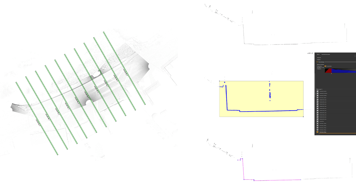
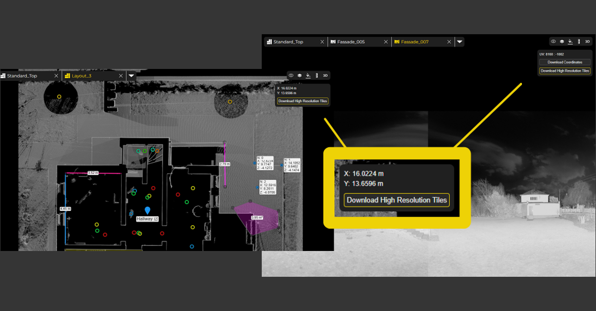
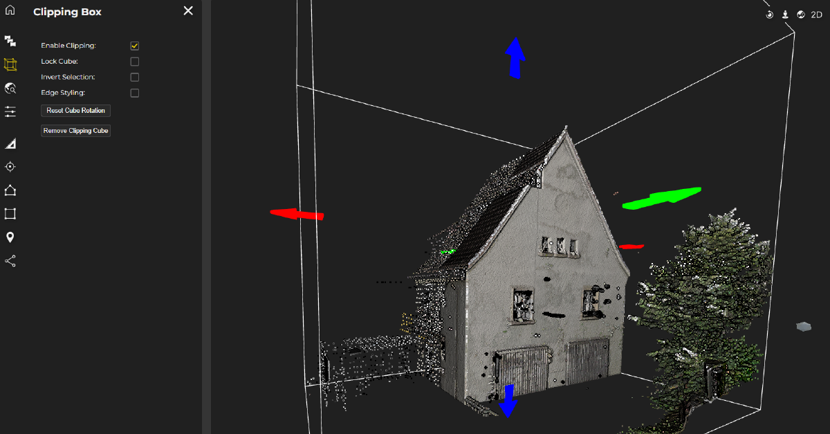
Origins 4.2 Updates:
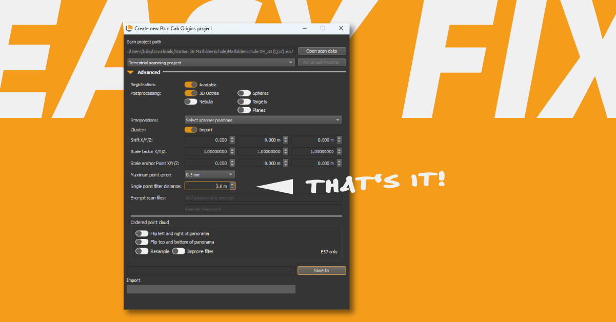
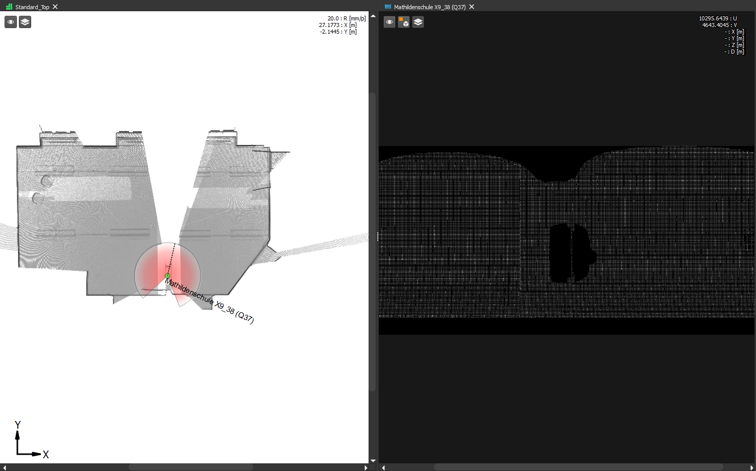
In addition to ongoing optimizations and broader compatibility with new data formats, we introduced many new features and implemented customer requests to make our point cloud software, Origins, even more powerful and intuitive.Nebula 2.0:
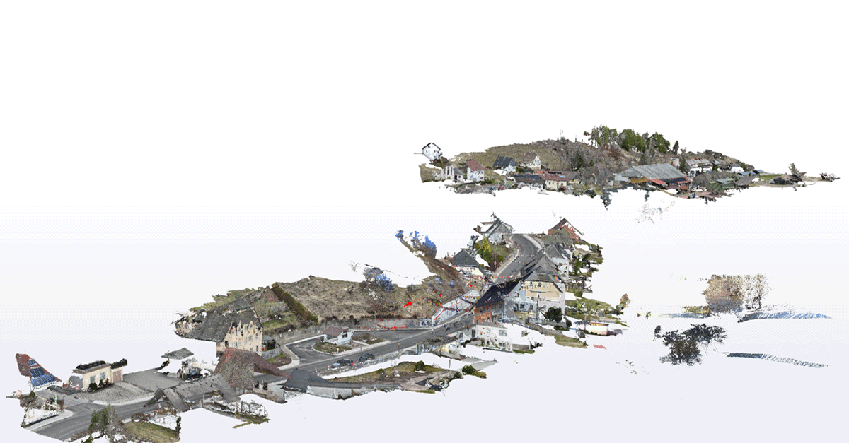
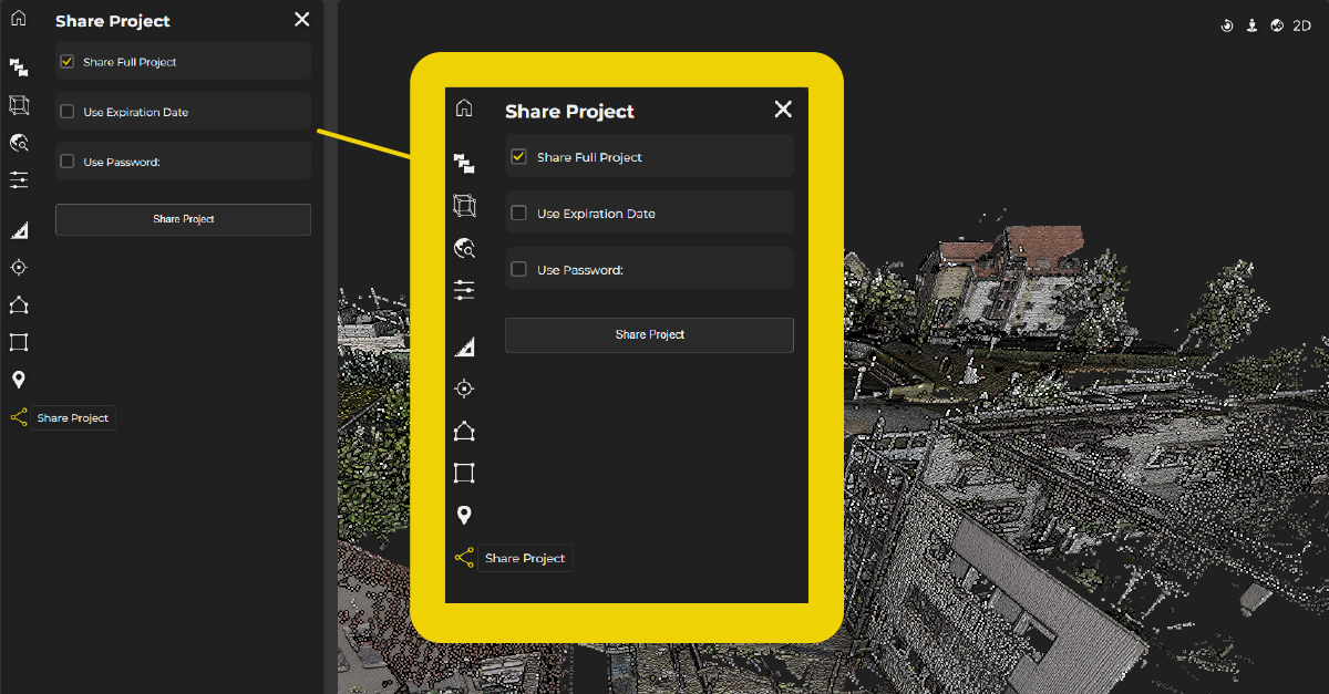
Our cloud solution for point cloud projects received a major overhaul.
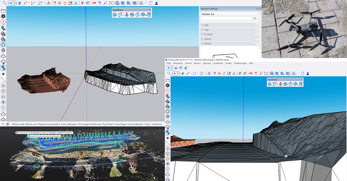
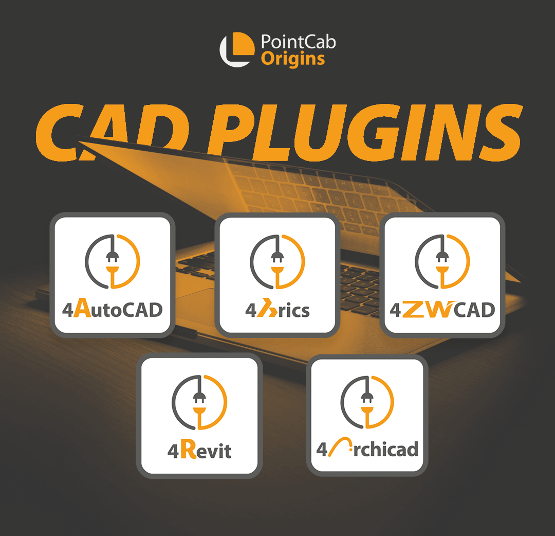
Alongside numerous new features, the interface has been redesigned to be even more streamlined and user-friendly. Sharing point clouds has never been easier.Point Cloud Plugins Update 3.0:
4AutoCAD, 4ArchiCAD, 4Brics, 4Revit & 4ZWCAD
With version 3.0, all our point cloud plugins received a brand-new import interface, making them more intuitive and easier to use. Naturally, each version is compatible with the latest release of its respective CAD software.
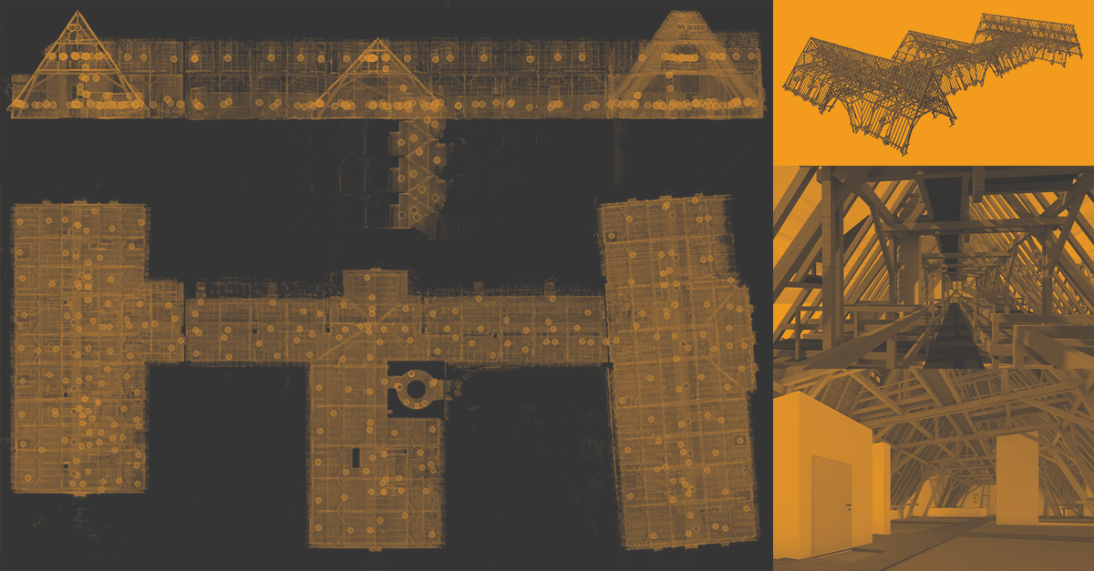
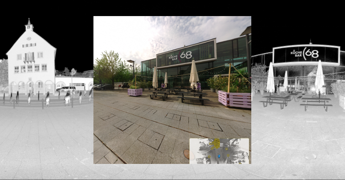
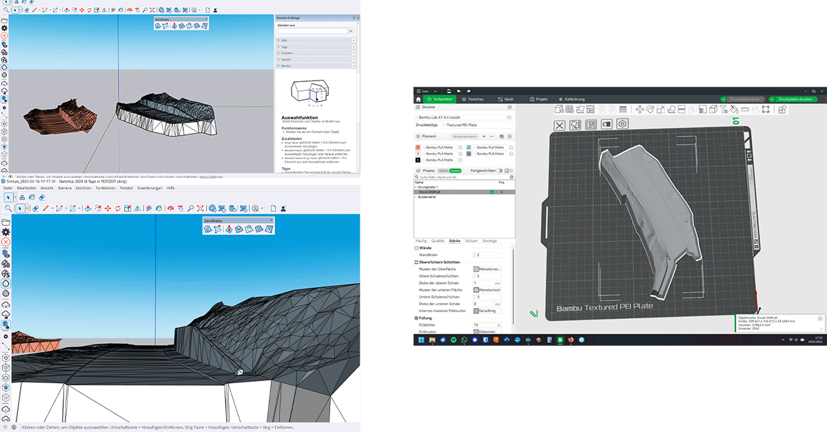
Our newest 4ArchiCAD 3.0 update, for example, includes multiple new features: multi-layer import, transparent orthophotos, XYZ data import as 3D points, and the new Update Mesh function.
A YEAR FULL OF CONNECTIONS – EVENTS,
NEW PARTNERS & RESELLERS
2025 was a year rich with connection – both in person and online. From GeoWeek in Denver with exciting live sessions featuring Mack (LIDAholics), to the Oldenburg BIM & 3D Days, the LSE Roadshow of our sister company in Stuttgart, the Energy Excellence Days, and major industry events like Intergeo in Frankfurt, we had countless opportunities to showcase our solutions, speak directly with users, and gather clear market insights.
A lot happened online as well. Our webinars introducing the new Nebula 2.0 cloud solution drew significant attention, underscoring the strong demand for scalable, modern workflows.
Partnerships remained a central theme. With new collaborations such as the XGRIDS bundle with Laserscanning Europe and Seiler Design Solutions in the US, as well as new resellers like GEOsat, we expanded our reach in 2025 and moved even closer to our customers than ever before.
FAREWELL AND TRANSITION
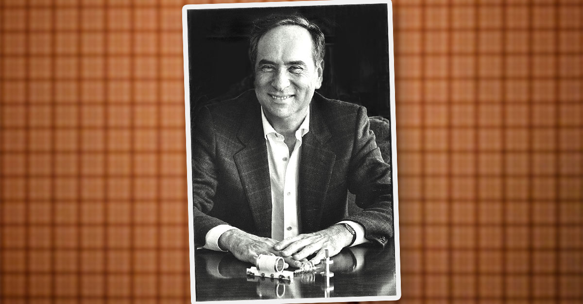
This year brought a painful loss. With great sadness, we had to say goodbye to our esteemed CEO and co-founder, Dr. Richard Steffen. After a long battle with cancer, our friend and CEO Richard passed away peacefully this summer surrounded by his family.
Following Richard’s wish, his long-time friend and business partner Eric Bergholz stepped in as the new CEO of PointCab. Eric and Richard shared a deep friendship since the founding of PointCab. With Eric – who is also the CEO of our sister company Laserscanning Europe – our future is in capable hands and will continue in the spirit of Richard’s vision.
MOVING FORWARD TOGETHER
Beyond the professional milestones, 2025 was shaped by real team moments. Our team-building event in sunny Valencia was a highlight that continues to resonate. The energy we built there carries into our everyday work – and it’s exactly what makes our team the driving force behind our success.
If you want to strengthen this environment, we’re excited to receive your application for the position of Technical Product Manager with a Customer Success Focus. Let’s head into the new year together.
As we say goodbye to 2025, we look forward to 2026 with determination – a year centered on innovation and teamwork.
WHAT'S LEFT TO SAY?
THANK YOU!
Despite everything heavy and emotionally difficult we had to face, 2025 was a strong year of growth, progress, and real achievements. We are grateful for all customers, partners, team members, and friends who stood by our side through this challenging time. The incredible support we received meant a great deal to us. Your compassion moved us deeply and helped us keep going. Thank you for every message, every conversation, and every moment of support.
Thank you to everyone who is part of the PointCab family. Here’s to an inspiring and successful 2026!


